介绍
Grid类用于生成桁架结构。
类结构
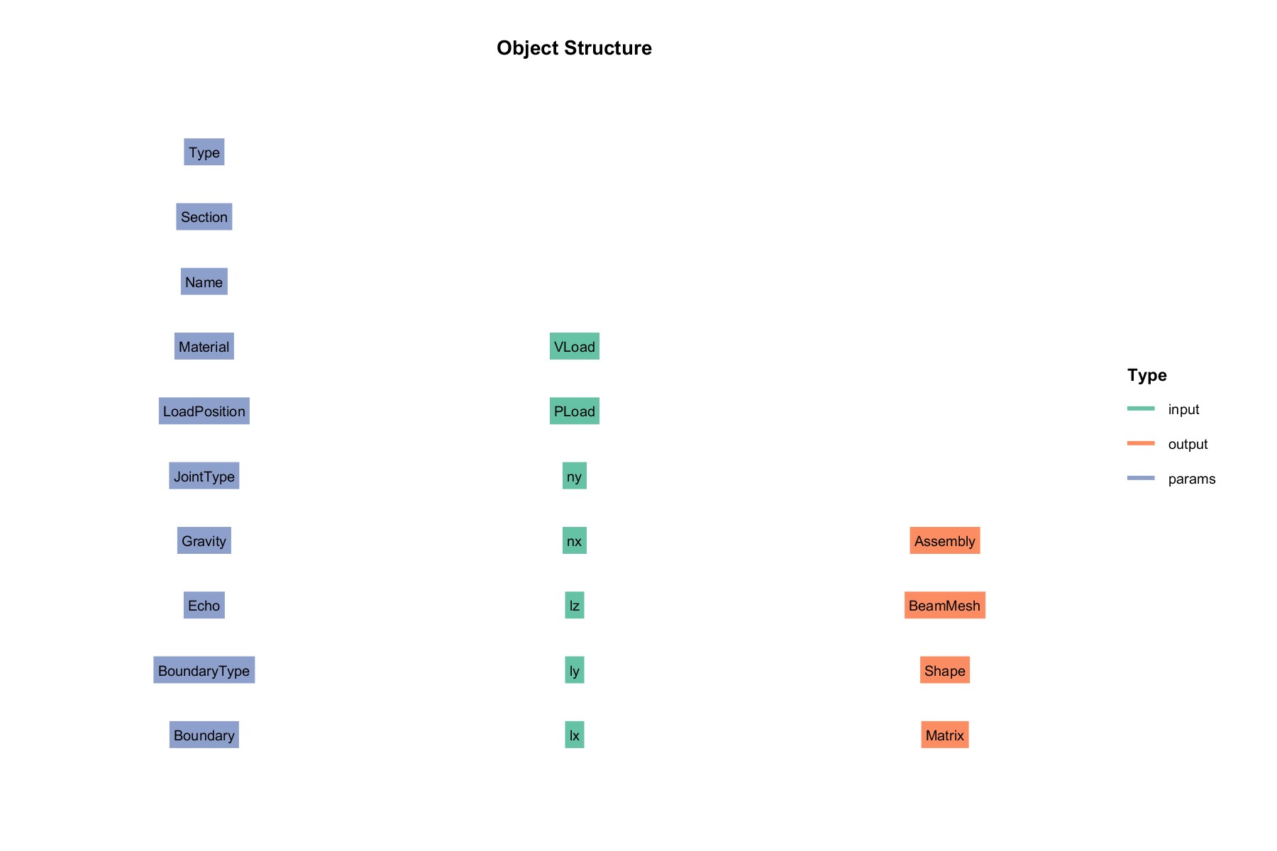
输入 input:
- VLoad : 可变荷载
- PLoad : 永久荷载
- ny:
- nx:
- lz: 高
- ly: 宽
- lx: 长
参数 params:
- Name : 名称
- Section :截面属性
- Material: 材料
- Type : 桁架类型
- LoadPosition : 载荷施加位置
- JointType : 节点类型
- Gravity : 重力
- BoundaryType : 边界类型
- Boundary : 边界
输出 output :
- Assembly : 装配体
- BeamMesh : 梁网格
- Matrix : 分类信息
- Shape : 外形
案例
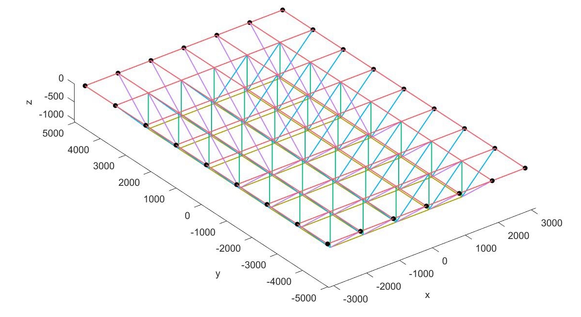
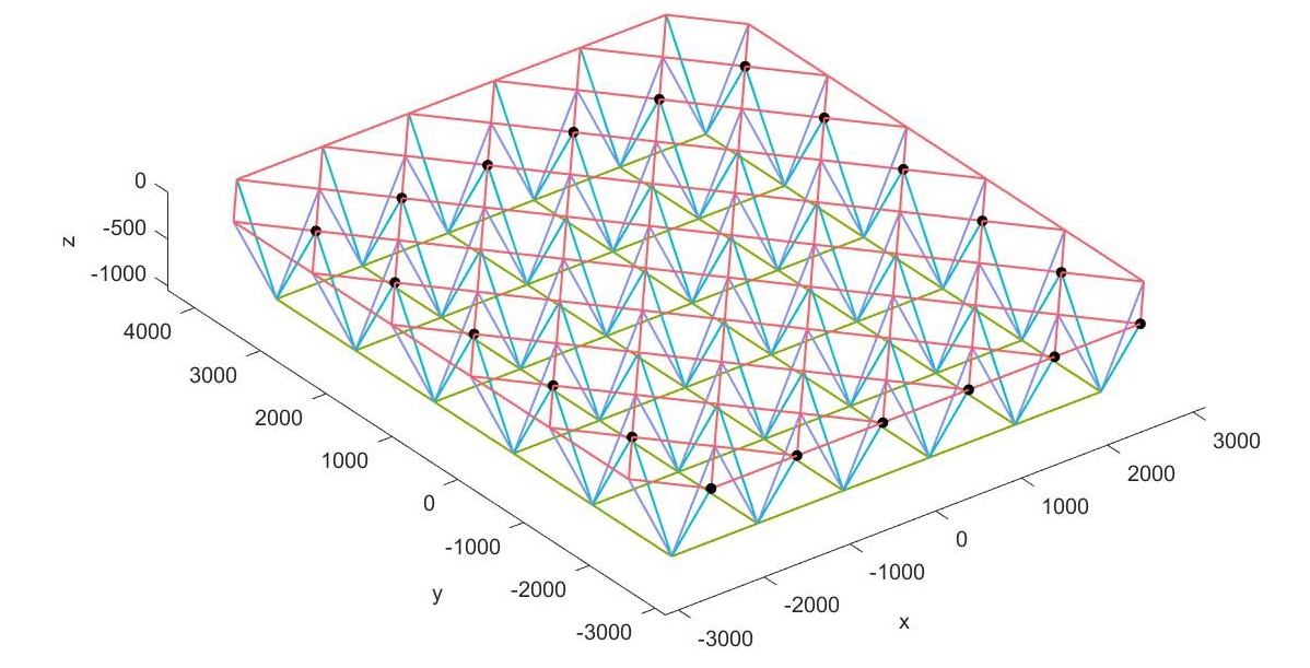
Create Grid Type 1 (Flag=1)
% Section
Section{1,1}.type="beam";
Section{1,1}.subtype="CTUBE";
Section{1,1}.data=[34,40];

Section{2,1}.type="beam";
Section{2,1}.subtype="CTUBE";
Section{2,1}.data=[34,40];

Section{3,1}.type="beam";
Section{3,1}.subtype="CTUBE";
Section{3,1}.data=[34,40];

Section{4,1}.type="beam";
Section{4,1}.subtype="CTUBE";
Section{4,1}.data=[34,40];

inputStruct.lx=1000;
inputStruct.ly=1200;
inputStruct.lz=-1000;
inputStruct.nx=7;
inputStruct.ny=9;
inputStruct.Load=200;

paramsStruct.Section=Section;
obj= structure.Grid(paramsStruct, inputStruct);
obj= obj.solve();

ANSYS_Output(obj.output.Assembly);
Plot3D(obj,'BeamGeom',1,'boundary',1,'load',1,'load_scale',0.3,'endrelease',1)
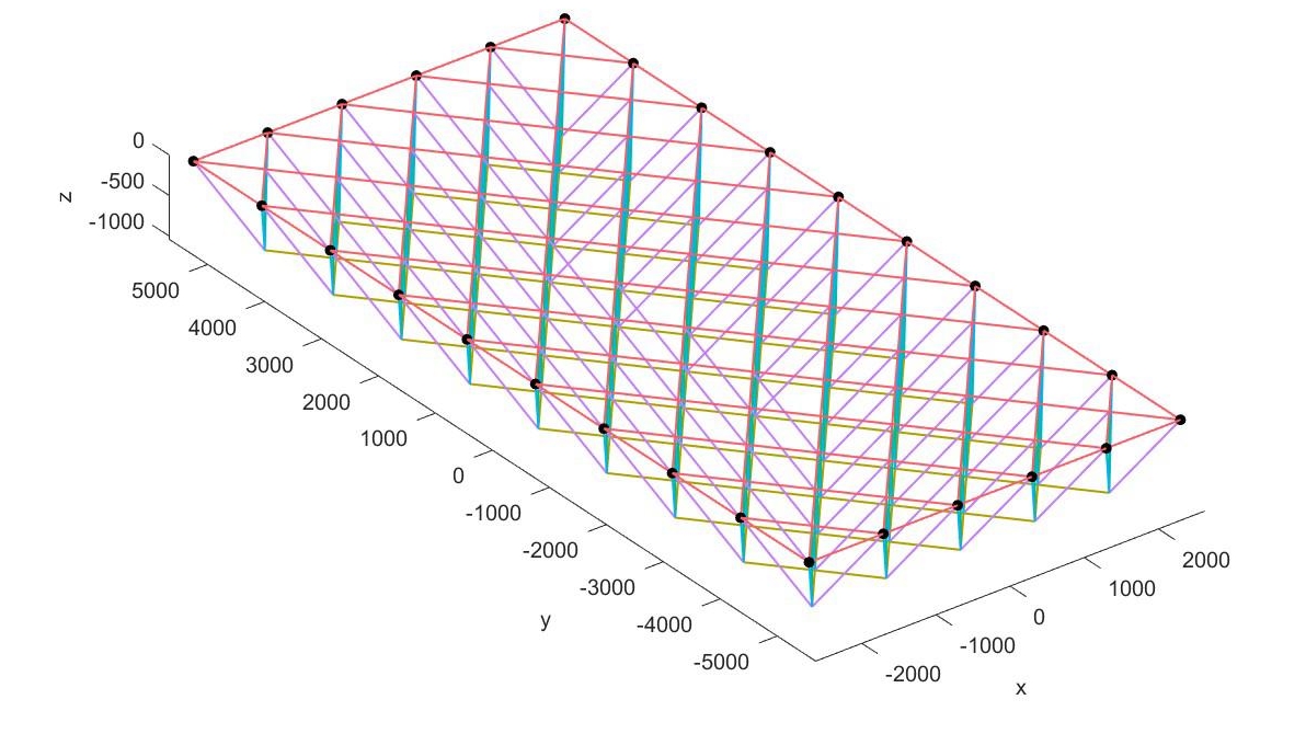
Create Grid Type 2 (Flag=2)
% Section
Section{1,1}.type="beam";
Section{1,1}.subtype="CTUBE";
Section{1,1}.data=[34,40];
Section{2,1}.type="beam";
Section{2,1}.subtype="CTUBE";
Section{2,1}.data=[34,40];
Section{3,1}.type="beam";
Section{3,1}.subtype="CTUBE";
Section{3,1}.data=[34,40];
Section{4,1}.type="beam";
Section{4,1}.subtype="CTUBE";
Section{4,1}.data=[34,40];

inputStruct.lx=1000;
inputStruct.ly=1200;
inputStruct.lz=-1000;
inputStruct.nx=6;
inputStruct.ny=10;
inputStruct.Load=200;

paramsStruct.Section=Section;
paramsStruct.Type=2;
paramsStruct.LoadPosition=2;

obj= structure.Grid(paramsStruct, inputStruct);
obj= obj.solve();
ANSYS_Output(obj.output.Assembly);
Plot3D(obj,'BeamGeom',1,'boundary',1,'load',1,'load_scale',0.3,'endrelease',1)
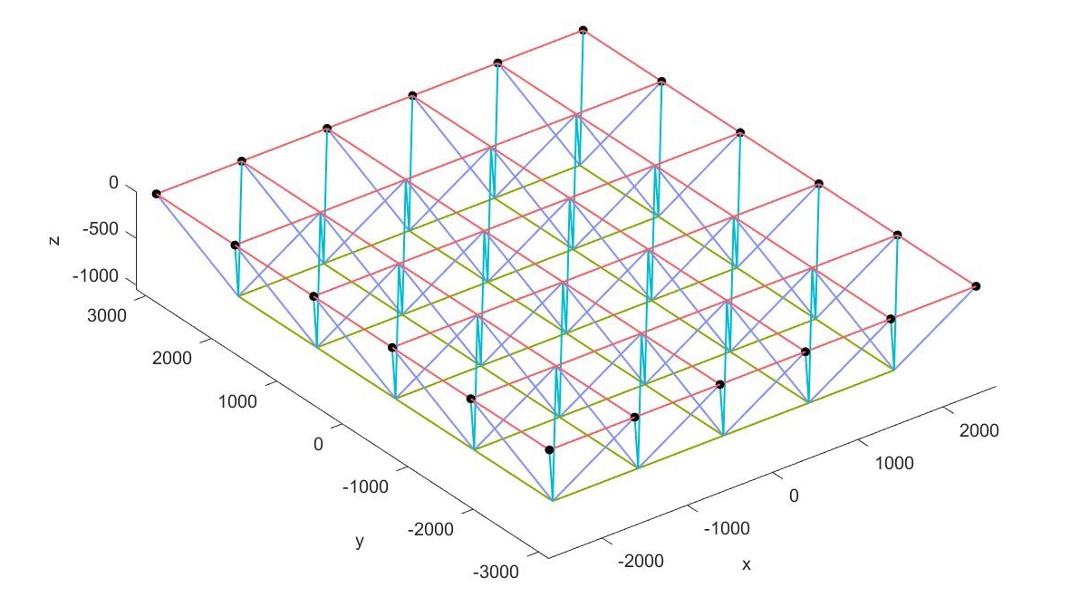
Create Grid Type 3 (Flag=3)
 % Section
Section{1,1}.type="beam";
Section{1,1}.subtype="CTUBE";
Section{1,1}.data=[34,40];
Section{2,1}.type="beam";
Section{2,1}.subtype="CTUBE";
Section{2,1}.data=[34,40];
Section{3,1}.type="beam";
Section{3,1}.subtype="CTUBE";
Section{3,1}.data=[34,40];
inputStruct.lx=1000;
inputStruct.ly=1200;
inputStruct.lz=-1000;
inputStruct.nx=6;
inputStruct.ny=6;
inputStruct.Load=200;
paramsStruct.Section=Section;
paramsStruct.Type=3;
paramsStruct.LoadPosition=2;
obj= structure.Grid(paramsStruct, inputStruct);
obj= obj.solve();
ANSYS_Output(obj.output.Assembly);
Plot3D(obj,'BeamGeom',1,'boundary',1,'load',1,'load_scale',0.3,'endrelease',1)
Create Grid Type 4 (Flag=4)
% Section
Section{1,1}.type="beam";
Section{1,1}.subtype="CTUBE";
Section{1,1}.data=[34,40];
Section{2,1}.type="beam";
Section{2,1}.subtype="CTUBE";
Section{2,1}.data=[34,40];
Section{3,1}.type="beam";
Section{3,1}.subtype="CTUBE";
Section{3,1}.data=[34,40];

inputStruct.lx=1000;
inputStruct.ly=1200;
inputStruct.lz=-1000;
inputStruct.nx=6;
inputStruct.ny=6;
inputStruct.Load=200;

paramsStruct.Section=Section;
paramsStruct.Type=4;
paramsStruct.LoadPosition=2;
obj= structure.Grid(paramsStruct, inputStruct);
obj= obj.solve();
ANSYS_Output(obj.output.Assembly);
Plot3D(obj,'BeamGeom',1,'boundary',1,'load',1,'load_scale',0.3,'endrelease',1)
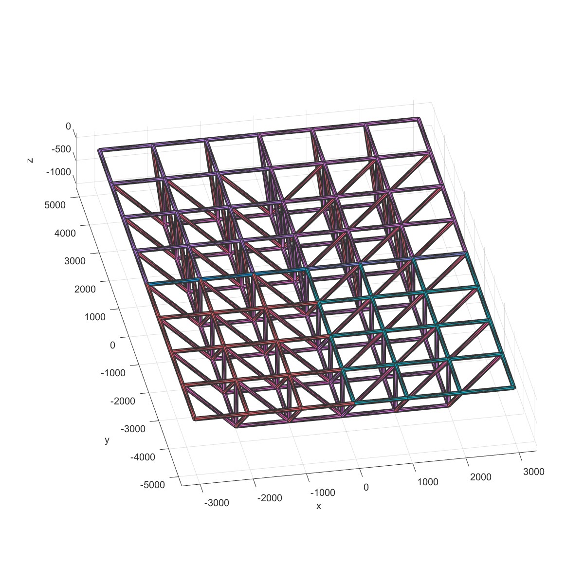
Output STL file (Flag=5)
% Section
Section{1,1}.type="beam";
Section{1,1}.subtype="CTUBE";
Section{1,1}.data=[34,40];
Section{2,1}.type="beam";
Section{2,1}.subtype="CTUBE";
Section{2,1}.data=[34,40];
Section{3,1}.type="beam";
Section{3,1}.subtype="CTUBE";
Section{3,1}.data=[34,40];
Section{4,1}.type="beam";
Section{4,1}.subtype="CTUBE";
Section{4,1}.data=[34,40];

inputStruct.lx=1000;
inputStruct.ly=1200;
inputStruct.lz=-1000;
inputStruct.nx=7;
inputStruct.ny=9;
inputStruct.Load=200;
paramsStruct.JointType=1;
paramsStruct.Section=Section;
obj= structure.Grid(paramsStruct, inputStruct);
obj= obj.solve();
OutputSTL(obj)
l1=Layer('Layer1');
l1=STLRead(l1,strcat(obj.params.Name,'.stl'));
Plot(l1);
参考文献
[1] 空间钢结构APDL参数化计算与分析
本网站基于Hexo 3-Hexz主题生成。如需转载请标注来源,如有错误请批评指正,欢迎邮件至 392176462@qq.com